English
- English
- Afrikaans
- Cymraeg
- icelandic
- беларускі
- Монгол хэл
- IsiXhosa
- Zulu
- Тоҷикӣ
- O'zbek
- Հայերեն
- Español
- Português
- русский
- Français
- 日本語
- Deutsch
- tiếng Việt
- Italiano
- Nederlands
- ภาษาไทย
- Polski
- 한국어
- Svenska
- magyar
- Malay
- বাংলা ভাষার
- Dansk
- Suomi
- हिन्दी
- Pilipino
- Türkçe
- Gaeilge
- العربية
- Indonesia
- Norsk
- تمل
- český
- ελληνικά
- український
- Javanese
- नेपाली
- Burmese
- Euskal
- Azərbaycan
- Македонски
- Lietuvos
- Eesti Keel
- Română
- Srpski језик

- Home
- About Us
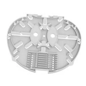
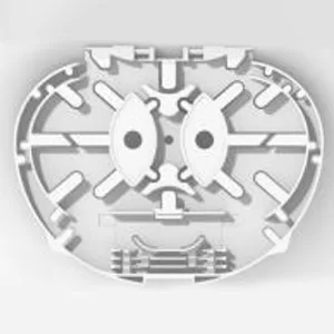
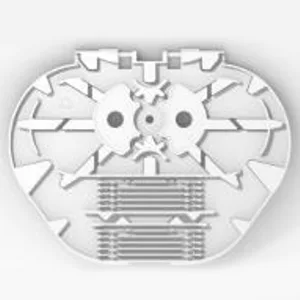
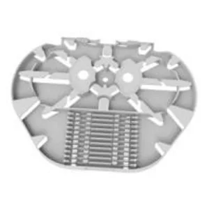
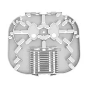
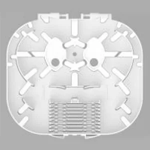
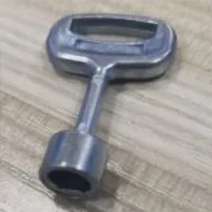
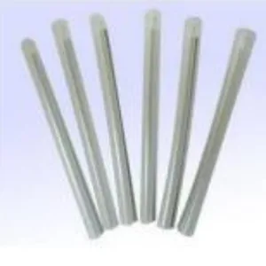
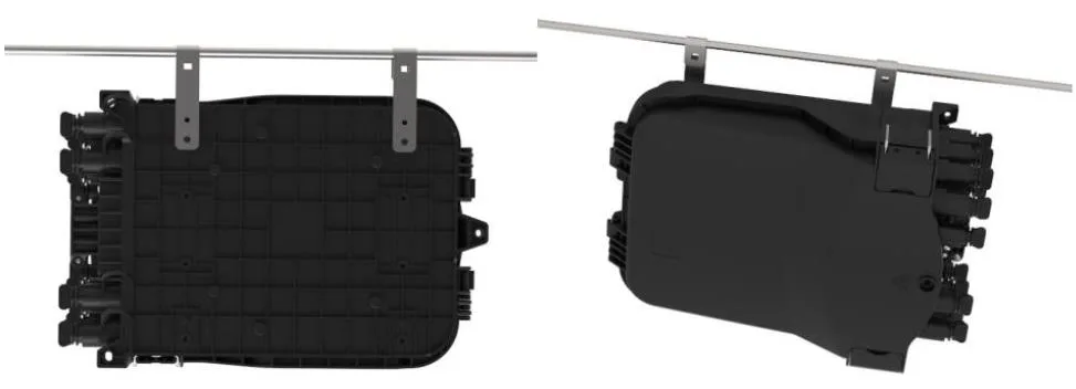
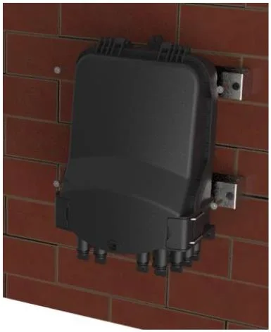
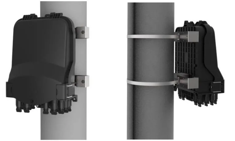
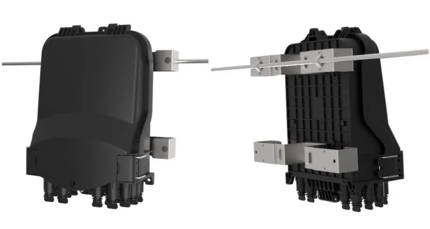
- ProductsUAV Fiber OpticOptical FiberIndoor Fiber Optic CableOutdoor Fiber Optic CablePatch Cord & PigtailFast ConnectorWaterproof ConnectorAdapterPLC SplitterCWDMODFFiber Optic Distribution BoxFiber Optic Splice ClosureTermination BoxFiber Optical AttenuatorConnectorSplitterDistribution Frame/Patch Panel


- News
- Download
- Send Inquiry
- Contact Us


")
")